How an old guy turned Victor's circuit diagram into a working breadboard.
PDF of breadboard interpretation
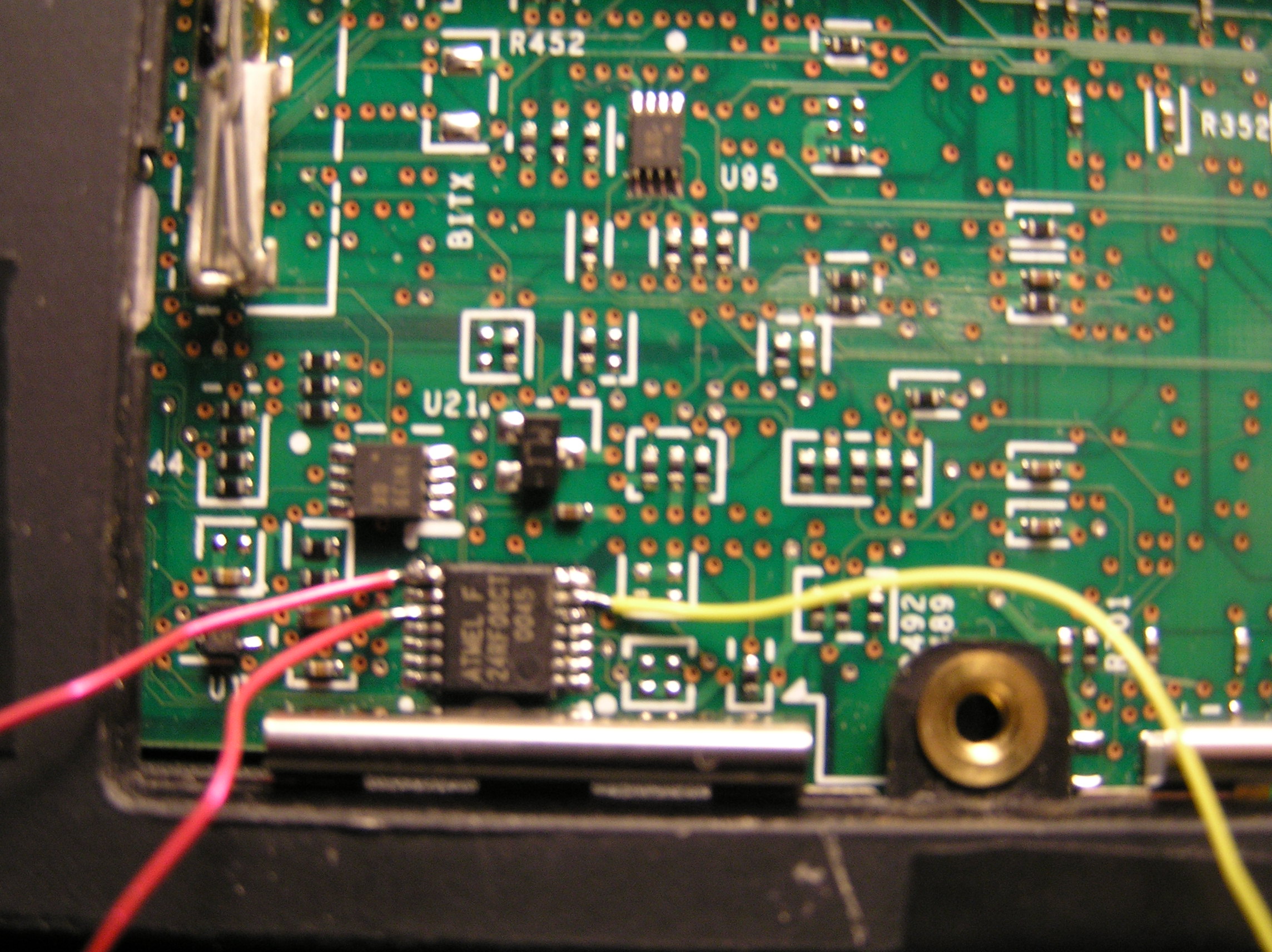
Bottom of T22 showing security chip with wires soldered
Close up of 24RF08 Security chip with SDA SCL GND wires soldered on
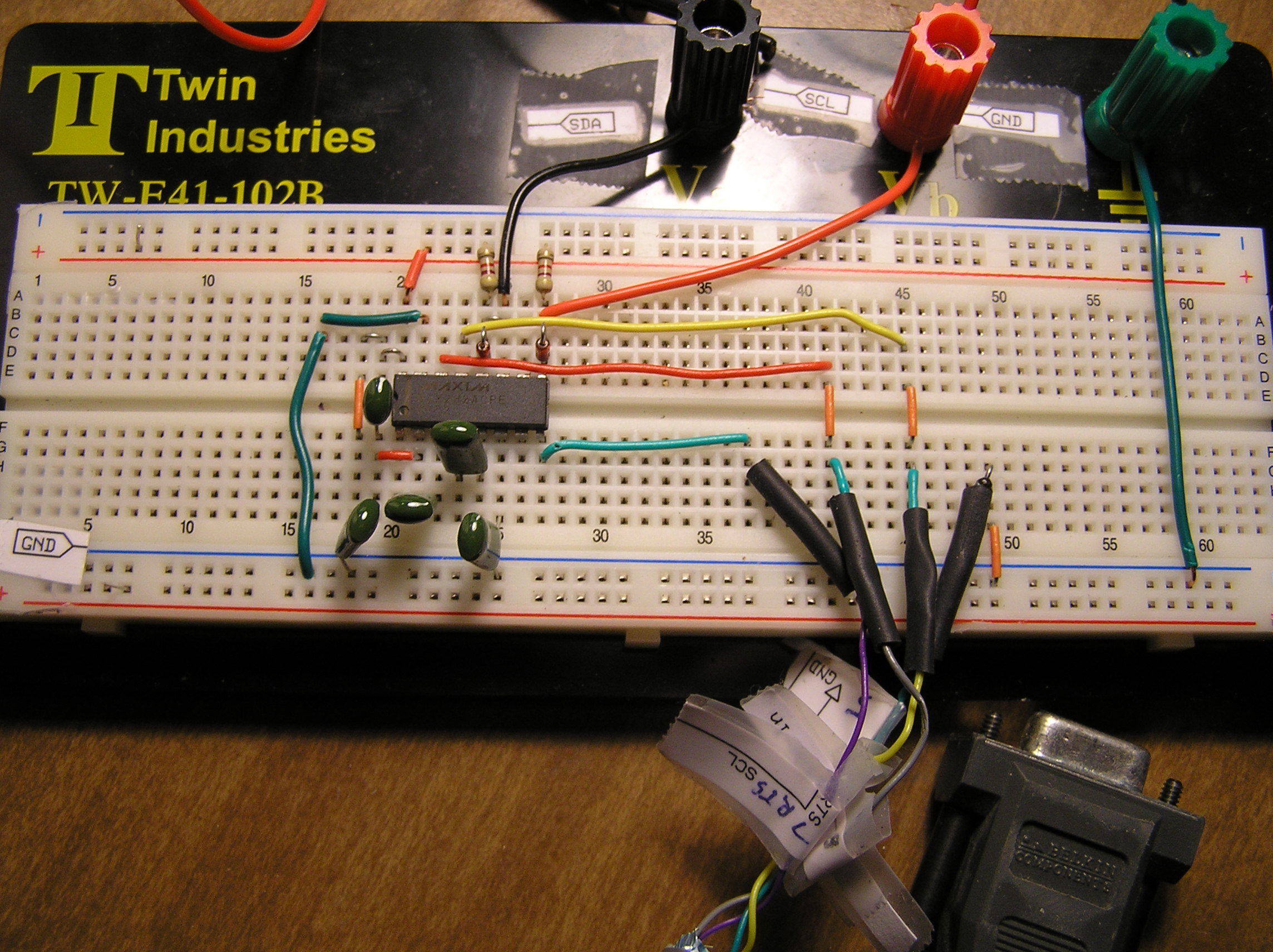
Main wiring area of breadboard
I used a breadboard for ease of wiring and figuring the circuit out. It took a few tries; been over four decades since I built a ham radio from scratch. I had a friend with a steady hand and fine-tipped iron solder on the wires to the 24RF08. (Note that the ground wire doesn't have to be soldered to the chip; you can clip to anywhere grounded metal on the frame.) I used fine Kynar coated magnet wire to go to the chip, taped it down, and then re-inserted the memory chips and gently put the door cover in place. The laptop needs to be right side up for the final steps <grin>.
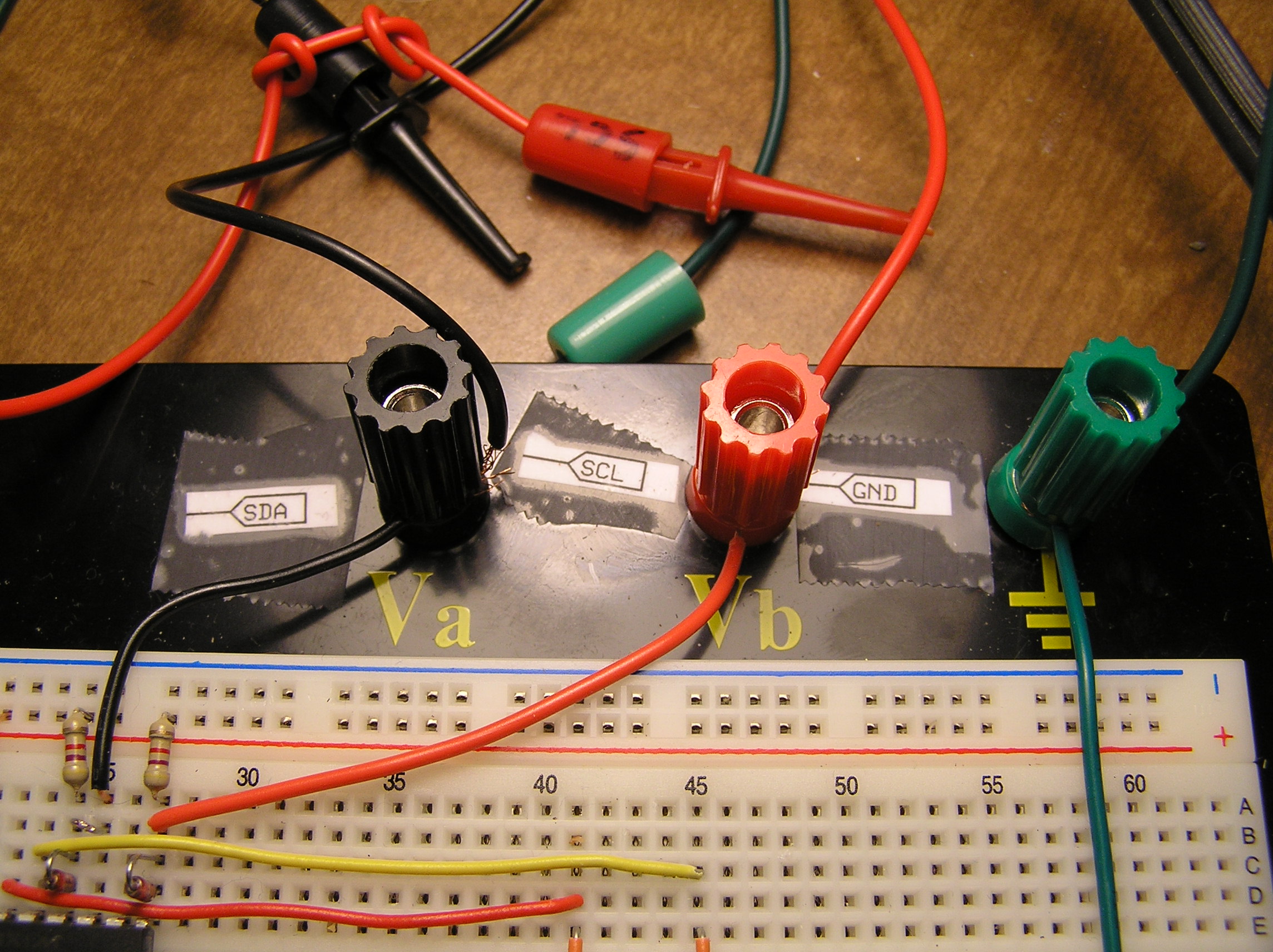
I used mini-grabber test leads to go from the breadboard to the leads from the 24RF08. They have very secure clips. Since their connection wires are stranded and the board wires are solid, I used the binding post connectors on the Twin Industries breadboard to connect them to jumpers from the board.
To connect to the serial port, I just cut the end off an old modem cable, stuck pins in the holes until I found which wires matched up with the four that were needed, and then soldered solid jumpers to these wires. This way I had a nice long cable with a good connection at the port end. Also, my cable plug was conveniently numbered (needed magnifier).
Note that the sequence is, connect the serial port, power on the 5V circuit, power up the laptop, connect the test leads to the wires from the security chip, run r24rf08.exe. Be sure to follow all of Victor's other cautions and instructions.
I'm sure there are lots of ways to realize Victor's design (which he modestly says is "just a classic max232 usage diagram" into a working circuit, and this surely may not be the best one. However, it did work for me, successfully reading the contents of the AT24RF08 security chip from my T22. Then the IBMPass2.exe read the .bin file and translated the scan code and gave me the correct supervisor password.
I can't say enough for Victor's generosity and skill. Like many, I searched the net for a solution to get into my laptop after the CMOS battery died. Having his circuit diagram was great; I hope someone will benefit from seeing how this old guy translated it into a working design.
Parts. Of course there are many sources. Here are the part numbers for the ones I used, purchased from Digikey, web-tronics, and radio shack:
MAX232ACPE-ND MAXIM 232A
Twin Industries 438-1047-ND BREADBOARD
1N4148FS-ND DIODE
OD472J-ND 4.7 K OHM RESISTORS
23PP410 .1uf polypropylene capacitor
MiniGrabber Test Lead Set/Deluxe Heavy Duty Set(M000F0004)
Enclosed 4 AAA Battery Holder Model: 27-411 Catalog #: 270-411
DB9 female cable -- spare from the parts box
Useful links: Soldering Guide
AT24RF08C Manufacturer's datasheet
Lessons in electronic circuits
The Electronics Club at Kelsey School. Lots of good info on theory and practice.